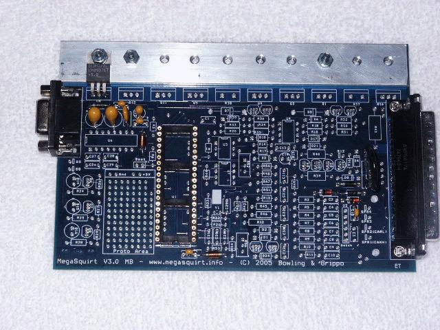
When you purchase a MegaSquirt kit, the components typically arrive individually packed, with part numbers. As a result, while you should verify that you have received all you ordered, it is not necessary to identify each item by color, markings, etc.
If you have questions about the specification or appearance of any item, check the part number at the Digi-Key site (http://www.digikey.com/) first. Entering the part number in their search engine will give you access to both the catalog information and the data sheet from the manufacturer.
Assembly Guide for MegaSquirt Main Board Version V3.0
MegaSquirt uses a number of components. These components are installed on the silkscreen side of the PCB, and in most case it will be easiest to solder them from the other side of the board. Electrically, the soldering works fine from either side, but as you get more components on the board, it gets harder to solder on the components side, forcing you to use the other side for soldering. There are three ways you can be sure of putting the right components in the right places with the right orientation. Most electronic parts have a standardized scheme for identification.
There are a large number of cryptic designations in building a MegaSquirt. Many of these have the form of a capital letter followed by a one or two digit number. These indicate components that are installed on the MegaSquirt main board (or stim, etc.) and are specific to each PCB. So R9 means resistor (R) number 9. Note that the main board has a R9, as does the stim, and they are different. Here are some examples:
There are also a number of X jumper locations (X1, X2, etc.). These generally specify a location on the board to solder a jumper, if you look at the board with all the components installed you should see a X1, X2, etc... still visible. They can also have other designations, such as JS4, or JS1.
The components themselves have a designation as well, and confusingly, these also often have the form or capital letters followed by numbers. For example, IRFZ44 = a specific component - the injector driver FETs.
Finally, there is the component part number, used to order the part from a supplier, and this can be different again.
For example, the injector driver FET for bank 1 is:
When you aren't sure, a search of the manual, and/or a quick look through the BOM should help you sort it out. Here are the parts used to assemble the V3.0 main board:
Color Code Legend
|
|
|
|
|
|
|
|
|
|
Please note that a few component values may have been tweaked - especially in the VR input circuit, but possibly others as well. Follow the Digi-Key BOM values for the current component specifications and use these over the values listed below.
|
QTY
Needed |
QTY
Ordered |
MegaSquirt References
|
Digi-Key
Part Num. |
Unit Cost
|
Circuit
|
Component Name
|
| 10 | 10 |
C1,C3,C13,C18,C19, C23,C26,C27, C28, C29, C31 |
399-4329-ND | 0.157 | Basic Components | Capacitor 0.1µF 50V 10% CER RADIAL - X7R |
| 3 | 3 | C11,C21,C32 | 399-2075-ND or 399-4326-ND | 0.18 | Basic Components | Capacitor 0.01µF 50V 10% CER RADIAL |
| 2 | 2 | C16,C17 | 399-1420-ND or 399-3584-ND | 2.60 | Basic Components | Capacitor TANT 22µF 25V 10% RAD |
| 4 | 5 | C2,C9, C10, C30 | 399-2083-ND or 399-4353-ND | 0.53 | Basic Components | Capacitor 0.22µF 50V 10% CER RADIAL - X7R |
| 1 | 1 | C20 | 399-4361-ND | 0.23 | Basic Components | Capacitor 0.033µF 50V 10% CER RADIAL |
| 2 | 2 | C14,C22 | 399-3559-ND | 0.71 | Basic Components | Capacitor TANT 4.7µF 25V 10% RAD |
| 1 | 1 | C24 | 399-1911-ND | 0.28 | Basic Components | Capacitor 47PF 200V 5% CER RADIAL |
| 1 | 1 | C25 | 399-1908-ND | 0.28 | Basic Components | Capacitor 22PF 200V 5% CER RADIAL |
| 6 | 10 |
C4,C6,C8,C12, C15 |
399-4202-ND | 0.127 | Basic Components | Capacitor 0.001µF 100V 10% CER RADIAL - X7R |
| 2 | 2 | C5,C7 | 399-2102-ND or 399-4389-ND | 1.40 | Basic Components | Capacitor 1.0µF 50V 10% CER RADIAL - X7R |
| 7 | 10 | D1-3,D9-11,D24 | 1N4001DICT-ND | 0.136 | Basic Components | Diode GPP 50V 1A DO-41 |
| 1 | 1 | D12 | 1N4749ADICT-ND | 0.36 | Basic Components | Diode Zener 24V 1W 5% DO-41 |
| 1 | 1 | D13 | 1N4742ADICT-ND | 0.36 | Basic Components | Diode Zener 12V 1W 5% DO-41 |
| 3 | 10 | D14,D15,D16 | 67-1102-ND | 0.098 | Basic Components | LED Red Translucent Round |
| 2 | 2 | D17,D18 | 1N5819DICT-ND | 0.39 | Basic Components | Diode Schottky 40V 1A DO-41 |
| 1 | 1 | D19 | 1N4734ADICT-ND | 0.36 | Basic Components | Diode Zener 5.6V 1W 5% DO-41 |
| 2 | 2 | D4,D8 | 1N4748ADICT-ND | 0.36 | Basic Components | Diode Zener 22V 1W 5% DO-41 |
| 2 | 2 | D5,D7 | FR302DICT-ND | 0.42 | Active flyback | Diode FAST REC 100V 3A DO-201AD |
| 3 | 3 | D6,D20,D21 | 1N4753ADICT-ND | 0.36 | Basic Components | Diode Zener 36V 1W 5% DO-41 |
| 2 | 2 | F1, F2 | RXEF050-ND | 0.48 | Spares | Polyswitch RXE Series 0.50A HOLD |
| 2 | 2 | L1,L2 | M8388-ND | 1.01 | Basic Components | Choke RF Varnished 1UH 20% |
| 1 | 1 | MOV1 | P7315-ND | 0.75 | Basic Components | Surge absorber 20MM 22V 2000A ZNR |
| 1 | 1 | P1 | A23305-ND/A32119-ND | 2.07 | Basic Components | Connector D-SUB RECPT R/A 9POS PCB AU |
| 1 | 1 | P2 | A23289-ND or A32103-ND | 4.38 | Basic Components | Connector D-SUB PLUG R/A 37POS PCB AU |
| 2 | 2 | Q1,Q5 | IRFIZ34GPBF-ND | 1.43 | Spares | HEX/MOSFET N-CH 60V 20A TO-220FP |
| 1 | 1 | Q16 | 497-2716-5-ND | 6.08 | High-Current Ignition Driver | IC DRIVER 340V 7.5A ISOWATT220 |
| 2 | 2 | Q2,Q4 | ZTX450-ND | 0.63 | Basic Components | Transistor NPN 45V 1000MA TO-92 |
| 2 | 2 | Q22,Q23 | ZTX553-ND | 0.67 | VR Sensor | Transistor PNP 100V 1000MA TO-92 |
| 2 | 2 | Q3,Q11 | 497-2629-5-ND | 1.05 | Basic Components | Transistor PNP 6A 100V HI PWR TO220AB |
| 9 | 9 |
Q6,Q7,Q8,Q10,Q13, Q14,Q15,Q19,Q20 |
2N3904FS-ND | 0.16 | Basic Components | Transistor NPN SS GP 200MA TO-92 |
| 2 | 2 | Q9,Q12 | TIP125TU-ND | 0.63 | Active flyback | Transistor PNP DARL -100V -5A TO-220 |
| 7 | 10 |
R16,R19,R26,R27, R29,R42,R55 |
1.0KEBK-ND | 0.056 | Basic Components | Resistor 1.0K Ohm 1/8W 5% Carbon Film |
| 5 | 5 | R2,R9,R10,R32,R36 | 1.0KQBK-ND | 0.056 | Basic Components | Resistor 1.0K Ohm ¼W 5% Carbon Film |
| 9 | 10 |
R1,R6,R14,R17,R21, R44,R48,R53,R54 |
10KEBK-ND | 0.056 | Basic Components | Resistor 10K Ohm 1/8W 5% Carbon Film |
| 3 | 5 | R22,R49,R50 | 100KEBK-ND | 0.056 | Basic Components | Resistor 100K Ohm 1/8W 5% Carbon Film |
| 2 | 5 | R11,R51 | 1.0MEBK-ND | 0.056 | Basic Components | Resistor 1.0M Ohm 1/8W 5% Carbon Film |
| 1 | 5 | R23 | 10MEBK-ND | 0.056 | Basic Components | Resistor 10M Ohm 1/8W 5% Carbon Film |
| 2 | 5 | R15,R20 | 22QBK-ND | 0.056 | Basic Components | Resistor 22 Ohm ¼W 5% Carbon Film |
| 2 | 5 | R4,R7 | 2.49KXBK-ND | 0.108 | Basic Components | Resistor 2.49K Ohm ¼W 1% Metal Film |
| 6 | 10 |
R18,R30,R31,R33, R34,R35 |
270QBK-ND | 0.056 | Basic Components | Resistor 270 Ohm ¼W 5% Carbon Film |
| 3 | 5 | R24,R25,R28 | 330QBK-ND | 0.056 | Basic Components | Resistor 330 Ohm ¼W 5% Carbon Film |
| 1 | 5 | R12 | 390H-ND | 0.046 | Basic Components | Resistor 390 Ohm ½W 5% Carbon Film |
| 1 | 5 | R13 | 4.7KEBK-ND | 0.056 | Hall/Coil(-Sensor | Resistor 4.7K Ohm 1/8W 5% Carbon Film |
| 1 | 5 | R3 | 51KEBK-ND | 0.056 | Basic Components | Resistor 51K Ohm 1/8W 5% Carbon Film |
| 2 | 2 | R37,R38 | TAH20PR050J-ND | 6.73 | Current Limiting | Resistor .05 Ohm 20W TO220 |
| 2 | 5 | R39,R40 | 1.0H-ND | 0.046 | Basic Components | Resistor 1.0 Ohm ½W 5% Carbon Film |
| 1 | 1 | R43 | 13FR010-ND | 1.46 | High-Current Ignition Driver | Resistor Current Sense .010 Ohm 3W |
| 2 | 5 | R45, R46 | 10KQBK-ND | 0.056 | Basic Components | Resistor 10K Ohm ¼W 5% Carbon Film |
| 2 | 5 | R47, R57 | 47KEBK-ND | 0.056 | Basic Components | Resistor 47K Ohm 1/8W 5% Carbon Film |
| 2 | 5 | R5,R8 | 2.2KQBK-ND | 0.056 | Basic Components | Resistor 2.2K Ohm ¼W 5% Carbon Film |
| 1 | 1 | R52 | CT94W104-ND | 1.68 | VR Sensor | Trim Pot 100K Ohm TOP ADJ |
| 1 | 1 | R56 | CT94W103-ND | 1.68 | VR Sensor | Trim Pot 10K Ohm TOP ADJ |
| 1 | 1 | U3 | 160-1300-5-ND | 0.32 | Hall/Coil(-Sensor | Optoisolator w/base 6-DIP |
| 1 | 1 | U4 | IXDI404PI-ND | 2.06 | Basic Components | MOSFET Driver LS 4A DUAL 8DIP |
| 1 | 1 | U5 | LM2937ET-5.0-ND | 1.65 | Spares | Regulator LDO TO-220 |
| 1 | 1 | U6 | 497-2055-5-ND | 1.39 | Basic Components | DVR/RCVR 5V RS232 16 DIP |
| 1 | 1 | U7 | LM2904NFS-ND | 0.50 | VR Sensor | OpAmp Dual SGL SUPP HS 8DIP |
| 1 | 1 | Y1 | 300-1002-ND | 0.28 | Spares | Crystal 32.768KHz CYL 12.5PF |
| 1 | 2 | NA | 4724K-ND | 0.93 | Active flyback | Mounting Hardware TO-220 |
| 1 | 1 | NA | AE7240-ND or AE10018-ND | 1.95 | Basic Components | Socket Machine Pin ST 40POS GOLD |
| 1 | 1 | NA | AE7216-ND or AE10013-ND | 0.72 | Sockets | Socket Machine Pin ST 16POS GOLD (Max232) |
| 2 | 2 | NA | AE7208-ND or AE10011-ND | 0.35 | Sockets | Socket Machine Pin ST 8POS GOLD (IXDI404PI) |
| 1 | 1 | NA | AE7300-ND or AE10021-ND | 0.55 | Sockets | Socket Machine Pin ST 6POS GOLD (4N25) |
| 3 | 5 | NA | 67-1044-ND | 0.072 | Basic Components | Bezel LED Panel 5MM BK Nylon 2PC |
| 1 | 1 | NA | 237F-ND | 2.29 | Cables | Connector DB-37 Female; |
| 1 | 1 | NA | 937GM-ND | 2.23 | Cables | DB-37 Hood; |
| 1 | 1 | NA | AE1020-ND | 5.35 | Cables |
DB-9 Straight-through cable (6.5 feet/2 meters) |
Note that some components needed for the optional circuits are included in the 'Basic Components' if they the same as some components used in the basic assembly. 'Spares' means these are basic components that you might you to have a few extra in case of a failure in assembly or tuning.
In the assembly instructions are tables indicating some of the standard schemes for identifying resistors and capacitors, and well as how to find the 'positive' leads on polarized components. Note that you can also use a multimeter to measure resistors, and some can identify the orientation of diodes. Finally, you can use the bags that the components come in to identify them, the component is specifically, if sometimes a bit cryptically, labeled.
The following is a step-by-step assembly guide for the V3.0 PCB MegaSquirt partial kit. Read through all of these directions first. Be sure to check off each step as you complete it - this way you can take breaks and know where you left off. The first time assembler of average skill can count on spending 8 to 12 hours assembling and testing the MegaSquirt V3.0 main board if they follow the instructions below. To assemble your MegaSquirt, you will need:
Assembly proceeds in functional blocks, with testing after each block. These blocks are:
| Power Supply Construction and Testing | (steps 1-23) |
| Serial Communications Construction and Testing | (steps 24-26) |
| Clock Circuit Construction and Testing | (steps 27-41) |
| Input Section Construction and Testing | (steps 42-55) |
| Output Section Construction and Testing | (steps 56-80) |
Each of these will be covered in turn.
A tip for those about to assemble their MegaSquirt: whenever possible, orient the numbers on the components (such as diodes) so that you can read the "important" part of them when it's all assembled. For example, with a diode 1N4753, try to make sure you can read the 4753 part of the number when the diode is installed in the PCB. With any luck it will never matter, but if a problem occurs, you'll be glad you did this.
Also, if you are unsure of a resistor value (sometimes it is hard to pick out the color on a resistor), then use an Ohmmeter to determine resistance - remember that most of these are 10% tolerance devices, so your readings may not be exactly as designated.
Power Supply Construction & Testing
1. Get ready for assembling your MegaSquirt. Plan on taking 6 to 8 hours for the average person with average skills doing a first time assembly.
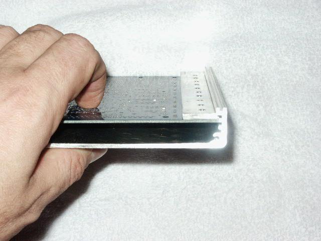
The wider lip of the case side is near the heat sink side of the board. This is to allow the top lid case to close. Mock it up by just sliding the board in the case with the end caps off, put on the top case half and slide the heat sink along the top, you will see why you need the fatter lip side of the bottom case half on the heat sink end. The aluminum should fit against the case lip for a little extra heat transfer.
2. Now we will install the two 'external' connectors, the DB9 and DB37. Install and solder the male DB-37 header (P2) {A23289-ND or A32103-ND} on the PCB. The connectors require a bit of force to 'snap' them into place. Solder all of the pins to give the headers the maximum physical strength. Make sure you do not bridge adjacent pins with solder. Also make sure you do not trap any debris under the connectors - once they are soldered in place, you will never get it out. Be sure to get the correct connector on the stim and MegaSquirt. Do not mix them up. Do NOT use gender changers to 'fix' incorrectly installed connectors - it WON'T work!
Then install and solder the female DB-9 header (P1) {A23305-ND or A32119-ND}.
Note that on current production boards, there is no jumper to connect/not-connect +5V to pin #9 on the serial connector. It has 5 Volts all the time. This is normally okay, however with MegaView there is a problem. Pin #9 goes into a dead short on the MegaView board. The quickest solution is to cut pin 9 off on the connector or cut the wire for pin 9 on the cable - its not needed for anything. In future revisions we will put a jumper on the supply to pin #9 for bluetooth wireless devices. If your main board has that jumper, you do not need to do anything other than remove the jumper to use MegaView.
3. Next, install the 40-pin DIP socket {AE7240-ND or AE10018-ND} for the processor - notice that the notch installs near the bottom of the board, corresponding to the PCB silk screen. The socket must be installed from the top of the board, and soldered from the bottom side. To prevent the socket from falling out while you turn the board upside down and solder, you can use a bit of scotch tape across the socket to hold it in place (this works for many of the ICs and some other components). Carefully solder the socket, and inspect each solder joint for shorts (to adjacent pins) or cold joints (solder applied to a joint the isn't hot enough to flow properly, typically they won't have a nice 'cone' to the solder).
Next, you are going to install the components that make up the power supply, and then verify operation:
4. The first part to install is the 'Perry' Metal Oxide Varistor MOV1 {P7315-ND}. This is a large flat disc, about an inch (~25mm) in diameter. It is soldered near the DB37 connector, and does not have a polarity, it can go either way around. This part protects the MegaSquirt from surges on the 12 volt line.
5. Install the capacitor C15 {399-4202-ND, 0.001 µF, 102 marking}. This goes near the MOV1 you just installed, between it and "Grippo" in the copyright notice. Note that the '1' night be obscured by a via.
6. Install and solder C16 {399-1420-ND or 399-3584-ND, a tantalum capacitor, 22 microFarads (µF), 226 marking} - make sure polarity is observed. It has a small “+” near the positive lead. The longer lead is also always the positive lead. It is located next to the DB9 connector.
7. Install and solder C17 {399-1420-ND or 399-3584-ND, tantalum, 22 µF} - make sure polarity is observed. The longer lead is positive on all of the capacitors. It is located next to the C16 capacitor you just installed, near the DB9 connector.
8. Install and solder C18 {399-4329-ND, 0.1 µF, 104 marking}. This installs near the DB9 connector, just above (closer to the heat sink area) the C17 capacitor you installed in the last step.
9. Install and solder C19 {399-4329-ND, 0.1 µF capacitor, 104 marking}. This installs near the CPU #1 pin.
10. Install and solder C23 {399-4329-ND, 0.1 µF capacitor}. This installs near CPU pin #21.
11. Install and solder C22 {399-3559-ND, 4.7 µF electrolytic} - make sure polarity is observed. It is located very close to C23.
12. Install and solder D9 {1N4001DICT-ND} - make sure banded end is installed correctly as per board. This installs near the DB9 connector, very near U5 on the heat sink. To do this, make sure the end of the diode with the band on it goes to the end of the silkscreen (at D9) that has the band nearest it.
13. Install and solder D10 {1N4001DICT-ND} - make sure banded end is installed correctly as per board. This is installed near the MOV1 you installed earlier.
14. Install and solder diode D11 {1N4001DICT-ND} - make sure banded end is installed correctly as per board. This is installed near the MOV1 you installed earlier.
15. Install and solder D12 {1N4749ADICT-ND, 24 volt Zener} - make sure banded end is installed correctly as shown on the printed circuit board. This installs very near D10 and D11.
16. Install and solder diode D13 {1N4742ADICT-ND, 12 volt Zener, 1N4742 marking} - make sure banded end is installed correctly as per the board. It is located above the column of capacitors above "Grippo" in the copyright notice.
17. Install and solder diode D19 {1N4734ADICT-ND, 5.6 volt Zener, 1N4734 marking} - make sure banded end is installed correctly as per the board. It is located in the upper right section of the board (near the DB37 and heat sink), below the Q14 and Q10 transistor and R32, R30 & R31 resistors.
18. Install and solder L1 {M8388-ND, inductor, 1µH, small coil of wire with leads}. It is installed near the notched end of the CPU socket. Space the inductor about 3mm off the PCB to avoid shorts on the traces underneath.
19. Install and solder L2 {M8388-ND, inductor, 1µH}. It is installed between the CPU socket and the DB9 connector. Space the inductor about 3mm off the PCB to avoid shorts on the traces underneath.
| The Boot Header {H1) on the board near Q9 is used to reprogram the CPU in MegaSquirt (not the tuning parameters, but the actually code that uses the tuning parameters). Leave it open, and do not jumper it. In most cases you won't need to touch it. Depending on what you want from your MegaSquirt, though, you may end up using the boot header to eventually to load customized code, such as MSnS-E, etc. To load new code, put a short piece of bent wire between the two H1 holes. Some people have put a momentary switch across the boot header, and place the switch so they can go into bootloader mode simply by pressing this switch while powering up, without opening the case. (If you do this, be sure it can't be pressed accidentally.) The instructions for loading new MegaSquirt code is here. |
20. Install and solder F1 and F2 {RXEF050-ND}. These are ½ Amp poly fuses (small yellow discs that look similar to some capacitors) that acts like a circuit breaker on the 5 Volt supply to the PCB from the regulator. F1 installs very near the DB9, in the middle of some of the capacitors you have already installed. F2 installs near the center of the DB37 connector, and very close to it.
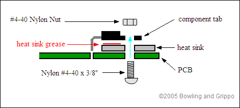
21. Install the voltage regulator U5 {LM2937ET-5.0-ND}. This part installs near the DB9 connector on the top of the board. Use heat-sink compound on the tab, and use the nylon screw and nut to fasten to the PCB. The leads go through the board and are soldered on the top side.
22. You now have the power supply assembled.
23. Before you go any further, you are going to verify that the supply is operational. To test, install a battery in the stimulator, and plug it into the DB-37 connector on the ECU board. Next, using a DMM (digital multi-meter) on DC VOLTS setting, check for 5 volts on the 40-pin processor socket you installed in step #3 (which is empty) - there should be 5 volts between pins 19 (ground) and 20 (+5), there should also be +5 on pin 1 and 31 (check against ground at pin 19), and ground potential on pins 2 and 32 (check against +5V on pin 20).
An easy way to probe this is by using a component lead that you cut from one of the resistors and wrapping around the DMM probe tip, then plugging into the socket. Remember that with the PCB oriented so the copyright notice is at the bottom (and can be read 'right-side up'), pin #1 on the 40-pin socket is on the lower right (at the same end with the notch), then goes up the 20 pins on that side, then over to the other side top, then down - it traces a counter-clockwise circle.
Check each box below as you measure the voltage between the ground pins across the top and the +5 pins down the left. You should get a voltage between 4.9 to 5.1 volts in each case (if your multi meter is accurate). Unplug the stimulator when finished.
| Pin |
|
||
| 2 | 19 | 32 | |
|
1 (5 Volt) |
____ | ____ | ____ |
|
20 (5 Volt) |
____ | ____ | ____ |
|
31 (5 Volt) |
____ | ____ | ____ |
If you don't pass the above tests, recheck all of the assembly steps in this section, verifying the correct components are installed with the correct orientation. If everything appears fine, check the troubleshooting tips.
Serial Communications Construction & Testing
24. Next, you are going to assemble the serial port link and verify operation. First step, install capacitors C26, C27, C28, and C29, {all 399-4329-ND, 0.1 µF, 104 marking} by soldering them in the appropriate locations near the DB9 connector.
25. Next, solder the serial communication MAX232, U6 {497-2055-5-ND} - note the proper orientation on the silk-screening. If you have bought a socket for U6 {AE7216-ND or AE10013-ND}, install it first, then place the chip in the socket. The notched end goes towards the DB9 connector, be sure to install in the proper direction. Solder it in place from the back side.
26. You now have enough to test the serial link. Do the following steps to verify operation:
If all these check out, you can proceed, otherwise you need to get a different cable. To repeat: On the cable, pins 2, 3, & 5 should all be connected and "straight-through".
Pins #1 and #9 have 5 volts on them; pin #1 has 5 volts because this is the standard serial specification (but not used with MegaSquirt), pin #9 has 5 Volts to power a bluetooth wireless device.
Pins 1, 2, 3, 5, & 9 are the only connected pins on the PCB.
The DB9 pin functions are:
i. On the PC, find and run HyperTerminal (Hyperterminal is usually under Start/Programs/Accessories/Communications, but if it is not there then search for a file called “hyperterm.exe”).
If you do not have HyperTerminal installed, you can get it from Hilgraeve, who wrote the original for Microsoft Windows. HyperTerminal Private Edition (HTPE) is what you want, and it's free for personal use. ii. When Hyperterm appears, click on the red telephone icon, and enter a save file name (anything you want, say, "megasquirt"). iii. When the "Connect To" dialog comes up, select under the "Connect Using" option the COM port to which the DB-9 cable is connected, i.e., COM1 or COM2. Do not worry about any of the other settings. Click OK. iv. Next, a dialog window opens with baud rate, stop bits, etc. Set the values according to the table below. Note: the last one, Flow Control, is very important – be sure to set it to None. Click OK.
Baud Rate 9600for MegaSquirt Data Bits 8 Stop Bits 1 Flow Control None
27. Install C1 {399-4329-ND, 0.1 µF, 104) and solder. This is located near pin #20 of the CPU socket.
28. Install and solder C20 {399-4361-ND, 0.033 µF, 333 marking}. It is located in a row of three capacitors above the L1 inductor you installed (above ".info" in the copyright notice)
29. Install and solder C21 {399-2075-ND or 399-4326-ND, 0.01 µF, 103 marking}. It installs beside C20.
30. Install and solder C24 {399-1911-ND, 47 pF, 470 marking}. This installs on the other side of C20.
31. Install and solder C25 {399-1908-ND, 22 pF, 220 marking}. This installs near the Y1 square silkscreen pad.
32. Install and solder R1 {10KEBK-ND, 10K, brown-black-orange}. This installs near pin #18 of the CPU socket.
33. Install and solder R3 {51KEBK-ND, 51K, green-brown-orange-gold/silver). This installs near pin #21 of the CPU socket.
34. Install and solder R6 {10KEBK-ND, 10K, brown-black-orange}. This installs near L2, by the 'Boot' jumper hole.
35. Install and solder R21 {10KEBK-ND, 10K, brown-black-orange}. This installs between C20 and C25.
36. Install and solder R22 {100KEBK-ND, 100K, brown-black-yellow}. This installs between the pad for Y1 and the components you have already installed nearby.
37. Install and solder R23 {10MEBK-ND, 10M, brown-black-blue}. This installs between the Y1 pad and the CPU socket.
38. Install and solder Y1 {300-1002-ND, 32768 Hz crystal, the very small silver can with the two tiny wires}. Note that Y1 is physically fragile, do not drop it. The crystal will fail to operate if it touches other components, so be sure it is clear of these. Bend the leads at a 90-degree angle so that the crystal lies parallel to the PCB. Note: You may want to “glue” the crystal to the printed circuit board with a cushion of silicone rubber adhesive (RTV) or 'hot glue'. A small "blob" on the under side of the crystal will cushion the crystal and dampen any mechanical vibrations. A small metallic ground pad is provided for this purpose.
39. Insert the CPU U1 {the 68HC908 for MegaSquirt). For the 68HC908 (MegaSquirt) processor the notch faces downward (line up with silk screen and socket notch). You may have to bend the leads inward a bit to get it into the socket - be careful not to break one off. Note that bending the CPU leads can be tricky. Your objective is to have the width of the CPU leads exactly match the width of the socket pins, before you attempt to firmly push the CPU into the socket. Ideally, you want to bend all pins at the same time. One technique is to hold the CPU with your thumb and index finger of each hand, so that one side of all the pins are against a rigid flat surface. Your thumbs are on the top of the CPU at each end and your index finger is underneath between the pins. By firmly tilting the CPU against the flat surface you will bend all the leads on one side of the CPU. Go slowly, a mini bend of a few degrees each time. Be careful not to bend the pins too far. Make several checks for fit in the socket as you go along. If you are having a difficult time visualizing this technique, place the CPU on a flat surface as if it were in the socket. Now turn the CPU up 90 degrees so that it is standing on the flat side of half its pins. A second method to bend all the CPU pins at once is to use an extra long needle nose pliers and grab all the pins at once. A twisting motion applied to the pliers will bend all the pins simultaneously. With care, this will also work if the needle nose pliers are only long enough to grab half the pins. Just make the bends in two steps.
40. You are now ready to test the operation of the processor. Plug in the DB-9 serial cable into the board and to the PC. Next we will ensure that the software is in place, on both the processor and the computer.
Note that the 68HC908 processors (for standard MegaSquirts and MSnS-E) already have the code loaded. Simply install MegaTune with all the default settings, and you should be ready to run.
To perform the tests at this step, you will also need to have MegaTune installed on your computer (this is also the program you will use to tune the fuel injection in the vehicle). To install the latest version of MegaTune on your computer:
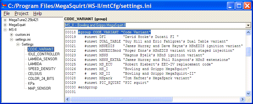
Click the link to find more information on MegaTune.
On the PC, run MegaTune by clicking on the icon on your desktop. Go into the "Communications" window and select the proper COM port (the "Verify ECU operation" does not operate, so do not be fooled). Exit this screen (back to the main window).
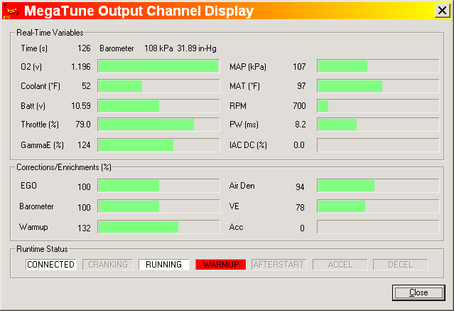
41. Plug the stimulator into the ECU. On the PC, click the "Realtime Display" under "Tuning" on the main menu, which brings up a new screen. Look at the "Time(s)" near the top left corner of the Realtime Display - it should be counting up, incrementing every second (it will roll over at the value of 255, back to zero). If the seconds count is there, you are running! If not, check the cable, make sure there is power, and check the COM port. The only other value on the screen which is working correctly is the "Batt V" box - it should be displaying the battery voltage (from about 7.0 - 8.5 volts, depending on the 9-volt battery condition). All other boxes will have nonsense for numbers.
Input Section Construction & Testing
42. Remove the processor from the 40-pin socket - use a thin screwdriver and pry it from the socket, first one end, then the other - place it back on the foam pad it was shipped with. Now, you are going to install all of the input sensor components.
43. Install and solder C3 {399-4329-ND, 0.1 µF, 104 marking}. This is located in the bottom right section of the board (near the DB37, furthest away from the heat sink) between the U2 column of holes and the SPR2(CANL)/SPR1(CANH) holes.
44. Install and solder C2, C9 and C10 {399-2083-ND or 399-4353-ND, 0.22 µF, 224 marking}. These install in the column of capacitors just above "Grippo" in the copyright notice on the silkscreen at the bottom of the board.
45. Install and solder C4, C6, and C8 {399-4202-ND, 0.001 µF, 102 marking}. These install in the column of capacitors just above "Grippo" in the copyright notice on the silkscreen at the bottom of the board.
46. Install and solder C5 and C7 {399-2102-ND or 399-4389-ND, 1.0 µF, 105 marking}. These install in the column of capacitors just above "Grippo" in the copyright notice on the silkscreen at the bottom of the board.
47. Install and solder R2, R9, and R10 {1.0KQBK-ND, 1K, brown-black-red}. These install in the column of resistors just above "&" in the copyright notice on the silkscreen at the bottom of the board.
48. Install and solder R5 and R8 {2.2KQBK-ND, 2.2K, red-red-red}. These install in the column of resistors just above "&" in the copyright notice on the silkscreen at the bottom of the board.
49. Install and solder R11 {1.0MEBK-ND, 1M, brown-black-green-gold). This installs in the column of resistors just above "&" in the copyright notice on the silkscreen at the bottom of the board.
Note: R11 and R10 are part of the EGO input circuit (with C10). It is very important that you do NOT install a capacitor across the sensor input before R11 (C10 comes after R10 and R11 and is fine). Some people have recommended adding such a capacitor to 'smooth' the sensor input. This will cause problems, especially with wide band analog outputs such as you find on Innovate's LC-1.
Also, if you have a wideband sensor/controller, be sure to ground the controller to the same point as MegaSquirt!
50. Next you need to make a decision. There are two input circuits for the tach signal:
The VR circuit is install in step 51, if desired.
In most cases, you should install both circuits, and make the selection between them with jumpers. However, if you do not want to install the Hall/optical/points circuit, skip ahead to step #51.
Read the MS EXTRA TRIGGER INPUT MANUAL --> http://www.msextra.com/manuals/MS_Extra_Ignition_Hardware_Manual.htm#hall
Note: this diode (D2) is needed only if the ignition system has a large offset bias - most systems do not have such a bias. So, to start, you can either solder in a jumper wire in this location, or, you can install the diode D2, and then install a jumper around the two leads of the diode - in effect shorting it out. The latter will allow you to snip the jumper later on if needed, putting the diode back in circuit. Solder the diode in observing the banded end as on the board, then solder a wire jumper across the diode itself.
If you later find you have an intermittent tach signal on the vehicle, but it doesn't work at all speeds or all temperatures in the car, check the Hall circuit modifications here: Hall input circuit mods
This input circuit is also used - with the modifications below - if you want to trigger off the negative side of the coil, since the points control the negative side of the coil's primary circuit. However, you can only trigger off the coil's negative terminal if you are NOT trying to control ignition timing. Do either 50a or 50b, not both.
51. As we noted in step 50, there are two input circuits for the tach signal. One takes the square wave input from a hall sensor, optical sensor, or points.
In most cases, you should install both circuits, and make the selection between them with jumpers.
However, if you do not want to install the variable reluctor (VR) circuit as well as the Hall circuit, skip ahead to step #52.
52. Select the tach input circuit with jumpers:
For the VR sensor:
|
OR(Do NOT install both sets of jumpers, chose one set or the other!)
|
For the Hall sensor, optical sensor, coil negative terminal or points:
|
Note for the Hall/optical/points circuit: The LED inside of the opto-isolator is fired by a signal provided by the ignition system. The pulses existing on an ignition, especially when pulled directly off of the coil primary, can spike to very high voltages. The return path of the LED is terminated to jumper pad XG1. This return path can either go directly to the board ground (by placing a jumper from XG1 to XG2), or, the return can be brought out of one of the jumper slots on the DB-37 connector (like SPR4 for pin #6), and then grounded with a separate wire on the DB-37 connector, thus isolating the ground. Note: for the ECU to work on the stimulator, then the XG1 terminal needs to be hooked to XG2, and right now we are doing stimulator testing, so install a jumper from XG1 to XG2.When you install the ECU, if you need isolation because the tach signal is resetting the ECU (for those installs tapping right off of the ignition coil (-) terminal), then you can remove this jumper and connect XG1 to SPR4, and ground this pin (#6 for SPR4) with a separate return wire. Note: if you are using a tach output from an aftermarket or many OEM setups, the tach signal is a nice +12V pulse - these will work fine with the XG1 terminal jumpered to XG2 in the install. Again: for testing right with the stimulator, hook XG1 to XG2. Later, after you install this on your vehicle, if you have reset problems, then remove this jumper and jumper XG1 to SPR4, and bring out a separate return ground wire to the ignition module/distributor on DB37 pin #6.
You may also need to do this if the Hall sensor input is noisy in the vehicle. To reduce noise, run the ground from the Hall sensor to one of the jumper slots on the DB-37 connector (like DB37 pin #6 for SPR4), then connect SPR4 to XG1. Remove the jumper to XG2. (Note that you will have to ground XG1 with a jumper wire to run on the stim.) Twist the signal wire (DB37 pin #24) and ground wire (DB37 pin #6) together all the way to the ignition module, this will further reduce noise in the signal.
53. The MAP sensor, U2 {MPX4250AP), is next. It mounts on the under side of the PCB, with the vacuum port facing the DB37 connector end of the PCB, and the markings on the sensor facing away from the PCB so you should be able to read the "MPX4250AP" marking when the sensor is installed. The leads are bent toward the PCB, and soldered on the top-side. The notch on the lead indicates pin #1 - this corresponds to the square pad on the PCB.
The MAP sensor is held to the PCB with two nylon screws - do not tighten the MAP sensor too tight, this will distort the case and introduce an offset in the readings by flexing the load cell inside the device. And, yes, solder the leads on the top side of the PCB. You will have to devise a scheme to run a tube from the barbed MAP fitting to your intake manifold.
54. Install and solder R4 and R7 {2.49KXBK-ND, 2.49K, red-yellow-white-brown-brown). These are the temperature sensor "bias" resistors. They install above the "&" in the copyright notice.
If you want to use other sensors, you can change the transfer-function files in the MegaSquirt 68HC908 processor by using EasyTherm to change MegaSquirt's code to match your temperature sensors.
55. Time for a little testing. Install the processor, hook up the stimulator, hook up the DB-9 to the board and PC, fire up MegaTune, and bring up the "Realtime Display" window. You should be able to see responses when you move the knobs on the stimulator.
First, look at the RPM - it should change when you move the RPM pots on the stimulator. Note that if you have installed the VR input circuit jumpers in step #52, the stim is not currently designed to put out the sort of signal (AC) the VR circuit expects. However, by adjusting the pots at R52 and R56, you might be able to get a useable signal into MegaSquirt. The RPM may not be stable at each end of 1000-6500 range, but it should be workable over that range, at least. Then you'll know that the rpm input circuit is functioning at it should.
All sensors should react to the corresponding pots on the stimulator. When the O2 pot is moved, the O2 voltage moves irrespective of the other settings. On the other hand, the EGO correction bar (or equivalent gauge on the tuning screen) WILL NOT move away from 100% unless you have the EGO correction parameters set properly and MegaSquirt senses the proper inputs to activate EGO correction. Note that if you have not connected a TPS to your MegaSquirt, (testing in car, for example) the TPS value will slowly creep up to a maximum value, and O2 correction will be disabled. You should check that MegaTune reads approximately the correct barometric pressure when no vacuum is applied. Below is a chart of the 'normal' barometric pressures for various elevations above sea level. MegaSquirt should generally be within 4 or 5 kPa of the values below at your elevation.
|
Elevation Above Sea Level |
Atmospheric Pressure |
|
|
Feet |
Meters |
kiloPascals |
|
0 |
0 |
101.33 |
|
500 |
150 |
99.5 |
|
1000 |
300 |
97.6 |
|
1500 |
450 |
95.9 |
|
2000 |
600 |
94.2 |
|
2500 |
760 |
92.5 |
|
3000 |
920 |
90.8 |
|
3500 |
1070 |
89.2 |
|
4000 |
1200 |
87.5 |
|
4500 |
1400 |
85.9 |
|
5000 |
1500 |
84.3 |
|
6000 |
1800 |
81.2 |
If you don't pass the above tests, recheck all of the assembly steps in this section, verifying the correct components are installed with the correct orientation. If everything appears fine, check the troubleshooting tips at the end of this assembly manual. You now have all of the inputs wired up. Next we are going to hook up the outputs and machine the case panels. Unhook the stimulator and DB-9 cable from the board, and remove the processor again.
Output Section Construction & Testing
56. Install and solder R14 and R17 {10KEBK-ND, 10K Ohm, brown-black-orange). These are located near the center of the PCB, in the column of components roughly aligned with Q9 on the heat sink.
57. Install and solder R16, R19, R26, R27, and R29 {1.0KEBK-ND, 1K Ohm, brown-black-red}.(Note - R26, R27 and R29 only for LED's.) R16 is near the MOV1 (a bit further away from the DB37). R19 to the right (closer to the DB37) of the resistors you installed in the last step (R14 & R17) on the other side of C13 and C14. R26, R27, & R29 are located near the LEDs at the DB9 end of the PCB.
58. Install and solder D3 {1N4001DICT-ND}. This is located near the center of the PCB, near R14 and R17. Observe the proper polarity.
59. Install and Solder D4 and D8 {1N4748ADICT-ND} - observe the proper polarity. These are located beside MOV1, a bit further away from the DB37 connector. (Note - do not install D8 if you are using a PWM idle valve.)
60. Install and solder R15 and R20 {22QBK-ND, 22 Ohm, red-red-black}. R15 is located below the Q1 location on the heat sink, R20 is located below the R38 location on the heat sink.
61. Install and solder R24, R25, and R28 {330QBK-ND, 330 Ohm, orange-orange-brown). (Note - only for LED's.) These are located very near the LEDs on the DB9 end of the PCB.
62. Install and solder the transistors Q2 and Q4 {ZTX450-ND}. (Note - do not install Q4 if you are using a PWM idle valve.) These are located to the left of the MOV1. The side of the transistor with the white label faces the DB37 connector. If you got this transistor from a distributor (as part of a kit) then they likely have special instructions for it (search the packaging or contact the distributor). Distributors sometimes make substitutions for various reasons, and thus their notes are important. If your Q2/Q4 are the standard Digi-Key part {ZTX450-ND}, but don't have a white label, then the side with the rounded edges is the 'curved side', which is oriented to be closest to the DB37 connector.
Be VERY careful soldering these small transistors, clean your tip, and make sure not to bridge the closely spaced pins.
If you use any other transistor other than PN2222AD26ZCT-ND or ZTX450-ND from the MegaSquirt/Digi-Key parts ordering page, you MUST check the pin orientation, as the order can be different for apparently identical parts!
|
Note - if you are using a PWM idle valve (Ford or Bosch 2 wire valve), these valves can not be operated with a relay. As a result, they need a higher capacity transistor installed.
Remove Q4, Q20, D8 and R39.
DO NOT install Q4 for use with PWM idle valves - it cannot handle the current directly for PWM idle valves. ('On/Off' type idle valves used with a relay are fine with the default Q4.)
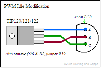
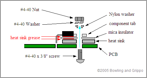
Instead, for a PWM idle valve, use a TIP120/121/122 transistor (such as Digi-Key 497-2539-5-ND, 74¢ ea.) mounted on either the heat sink (if you have a spare spot) or the case. You should use a mica insulator (4724K-ND, 93¢) with heat sink grease as well. Run wires to the Q4 connections as shown below:
Do not install Q20, do not install D8, and jumper R39 as well. You will also have to put a 1N4001 diode across the PWM Idle valve itself - the banded end goes to the 12 Volt supply, the non-banded end goes to the lead that goes to MegaSquirt (this diode is for flyback purposes on the idle valve). |
63. Install C13 {399-4329-ND, 0.1 µF, 104) - and solder. This is located a bit closer to the heat sink, and a bit closer to the DB9 than Q4.
64. Install and solder C14 {399-3559-ND, 4.7 µF). This is located just a bit further away from the heat sink than C13, which you installed in the last step. Observe polarity. Recall that the positive lead has a small + near it on the body of the capacitor.
65. It is choice time again. In this case, you will decide whether to populate the high-current ignition driver circuit. This circuit can be used to drive a single coil in a distributor application. In conjunction with an appropriate input signal (from a VR, Hall, or optical sensor, or even points), it allows you to eliminate a separate ignition module, such as a GM HEI 7 or 8 pin module, and run the coil directly from MegaSquirt.
Read the MS EXTRA SPARK OUTPUT MANUAL --> http://www.msextra.com/manuals/MS_Extra_Ignition_Hardware_Manual.htm#msdout
66. Install and solder U4 {IXDI404PI-ND}, the FET driver. This is located near the Q3 location on the heat sink. If you bought a socket {AE7208-ND}, solder it in place and insert the chip. Be sure to orient it correctly, the notch or dot on the chip goes to the notched end on the silkscreen; this end is closest the heat sink.
67. Install D17 and D18 {1N5819DICT-ND}, the Schottky diodes. These are located on either side of the FET driver (U4) you just installed. Make sure the band on the diode matches the silkscreen.
68. Install and solder D21 {1N4753ADICT-ND}. This is located just a bit further away from the heat sink than D17. Make sure the band on the diode matches the silkscreen.
69. Once again you have a choice to make about whether to install certain components. In this case, you need to decide if you wish to install the PWM flyback damping circuit as well as the standard flyback circuit. The PWM flyback damping circuit is useful primarily for those running pulse width modulation (PWM) with low-impedance injectors. However, it will work fine if you install it with high impedance injectors. If you prefer to install only the standard flyback circuit, skip ahead to step #70: To install the PWM flyback damping circuit:
70. To install the standard flyback circuit:
71. It is choice time yet again. You have to decide whether to install the current limit circuit for driver FET protection. This clamps the current to ~14 Amps, and it is recommended that most people install this. To install the current limit protect circuit:
72. IF you installed R37 and R38 in the previous step, install Q14 and Q15 {2N3904FS-ND} - otherwise you can leave then out. It does no harm to install them in every case, however. Use a clean tip, and be careful not to bridge the closely spaced pins.
73. Install D5 and D7 {FR302DICT-ND}. These diodes should be mounted about 2-4mm off the board. Make sure the band on the diode matches the silkscreen. These are located near R38 and Q3.
74. Install Q19 and Q20 {2N3904FS-ND}. These are located in line with the existing transistors (Q2 and Q4) to the left of the MOV1. Be very careful when soldering them, use a clean tip, as the pin spacing is very tight. (Note - if you are using a PWM idle valve, do not install Q20.)
75.Install R39 and R40 {1.0H-ND, 1 Ohm, brown-black-gold}. These are located on either side of the transistors (Q19 & Q20) that you installed in the last step. (Note - if you are using a PWM idle valve, install a jumper in place of R39).
76. Install Q1 and Q5 {IRFIZ34GPBF-ND}, the FETs (field effect transistors, used to drive the injectors). These are bolted to the heat sink, be sure to use heat transfer compound between the FET and the heat sink. These are insulated case variety, so they mount directly on the heat sink.
77. Install and solder Q6, Q7, and Q8 {2N3904FS-ND}. (Note - only for LED's.) Follow the silkscreen to orient the flat side of these transistors, which faces the DB9 end of the PCB.
78. We now have everything installed, other than the LEDs - these mount on the case ends.
79. Now, take one of the case halves, and install the PCB in the second-down slot down from the top. Note: The wider lip of the case side is near the heat sink side of the board. This is to allow the top lid case to close. The aluminum should fit against the case lip for a little extra heat transfer.
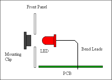
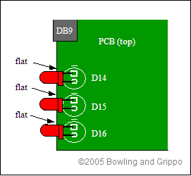
80. Next, mount the LEDs - D14, D15, and D16 {P301-ND} to the case font, and bend the leads down to the board and solder. The flats on the LEDs (the side with the short lead) faces the DB9 connector. First, install the LED holders on the front panel, through the front. Next, the LEDs press into the rear of the holder. Mount the case front panel to the case half (which has the PCB). Orient the FLAT on the side of the LED lip (the side with the shorter lead) towards the DB-9 socket (each LED). You will see that the PCB silk screen also has a "dash" above the LED circle symbol indicating the side of the flat. Bend the LED leads down to enter the PCB holes for them - you will have to do a trial fit, then trim the leads down a bit. See the illustrations below. Then solder the LEDs to the PCB from the top of the PCB. It is a little tricky - take your time.
If you don't pass the above tests, recheck all of the assembly steps in this section, verifying the correct components are installed with the correct orientation. If everything appears fine, check the troubleshooting tips.
Note: normal MAP readings in kPa for the MegaSquirt when the engine is not running (or is on the stimulator) should be somewhere around 85-103, depending on your elevation. You can check the tuning section of this manual for the details of how pressure varies with elevation. This is a good time to clean the excess flux from the board. A common problem with boards that were working and quit for no apparent reason is flux residue. Remove the processor. Wash your board with:
Compressed air can speed the drying process, but be aware that some of the commercial compressed air cans have a solvent that can saturate any remaining flux and cause problems.
If you want to seal the finished board, use a conformal coating. Wait until you have tested the board thoroughly though. If you do not think you will be doing much repair work on the board, you can not beat silicone conformal coating. It does require some digging to get it off for repair, however. Avoid the urethane coatings, as they are considered permanent and are a pain to try to work through.
This should slow down or prevent "solder bloom" and other deterioration of the PCB. Condensation is a fact of life for an outdoor component undergoing temperature changes. You can solder right through the stuff and the residue cleans well with pure grain alcohol.
Slide the completed PCB into the case. The wider lip of the case side is near the heat sink side of the board. This is to allow the top lid case to close. Put a bit of heat sink compound between the heat sink and the case to enhance the cooling of components by using the case itself as part of the heat sink.
Your next job is to mount the unit in the car, tune, and go!
You cannot install the MegaSquirt box under the hood. Engine bay temperatures are just too high. The recommended place to install the MegaSquirt box is in the passenger compartment (like under the seat, kick panel, etc), this is where many OEM boxes are located. In addition, you will need access to the RS-232 serial connector for tuning, which is hard to access under the engine hood. If you put the MegaSquirt box in the passenger compartment, you will not have heat-related problems (unless you mount it directly in the path of the air stream of the car heater).
MegaSquirt should be connected with a pass-through hole (and grommet) to the engine compartment for the wiring to the injectors, sensors, fuel pump, etc. If you have put your MegaSquirt together, but it does not work, don't panic, just follow the troubleshooting instructions.

Note that MegaSquirt is a bank fire injection system, you connect half the injectors to the driver for one bank (pins 32/33), the other half to the other driver (34/35) [4 are shown]. See: the FAQ. You can connect them in any order. For troubleshooting ease, having each bank on a separate driver might help. However, you might want to separate them into alternates in the firing order, which some people have claimed is theoretically slightly beneficial. As an example, on V8s with bank fire systems, manufacturers typically run one bank off one driver, regardless of the firing order. The advantage of doing it that way is it makes troubleshooting easier.
All MegaSquirt installations must have an input (tach) signal to determine engine speed. This signal comes in on pin #24 of the DB37. A variable reluctor (VR) input (tach) sensor is shown (above) for the input. To use a Hall sensor, optical sensor, or points trigger, you connect the signal to the same input pin (DB37 #24) as the VR sensor. You must ground the VR other lead of the sensor as well, and pin #7 is shown for this. However, pin 7 is not a 'dedicated' or specialized ground for the VR sensor, it just happens to be a ground. The VR sensor can be grounded to any pin that connects to the board's ground, and it can be connected externally (I.e., in the DB37 connector for the harness, or even in the wiring loom).
The DB37 pin #36 is an output, used to control an ignition module, or control a coil directly (if the high current ignition driver circuit is installed). It only needs to be connected if you are controlling ignition timing and dwell.
If you are using PWM Idle control, you cannot use the FIdle relay on the relay board, and have to jumper the relay socket. The jumper goes from the relay socket hole nearest the CB1 polyfuse to the relay socket hole nearest DB37 pin #4.
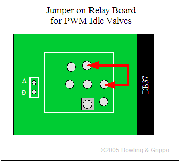
This provides a direct signal from the MegaSquirt to the PWM idle valve. Note that the transistor on the V3 main board is NOT sufficient to drive a Ford PWM Idle valve (as well as many other makes) directly. You MUST use the another transistor (such as a TIP120/121/122) that control the valve. You can use the proto area to connect this circuit, or you can build it externally.